แสดงบทความที่มีป้ายกำกับ Oscillator Generator แสดงบทความทั้งหมด

The 60hz calibration frequency standards for digital clock by MM5369

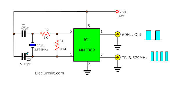
This is digital circuit, Pulse Generator 60HZ and TP 3.579MHZ. It use IC MM5369 – 8Pin easy use. power supply 12V.Out put Frequency 60HZ Pulse Generator. (PIN 1)
This is calibration frequency standards for digital clock circuit.
When you have finished building your digital clock circuit kits, with any ICs number. But how to
which normally we will be get the standard frequency signal of AC power line 60Hz (North America the power line frequency is 60 cycles per second or 60 Hertz) that is a sine wave and then is converted with the Pulse Generator circuit become to square wave form of 60 Hz .
But when we need to use it in the car or others DC power supply. How to it still work well?
We so built the circuit of the pulse generator of 60Hz, to replace the old ways. You may also be adapted to backup set , when the power goes out. We do not have to waste time re-scheduling.[...]
60HZ CLOCK Pulse Generator by IC MM5369
Read more source: http://www.eleccircuit.com/60hz-clock-pulse-generator/

cmos crystal oscillator circuit

Crystal Oscillator with IC Digital 74HC04


The circuit above is a parallel resonant oscillator circuit. ... 32.768 KHz oscillator using a watch crystal · Cmos Logic Clock Oscillator ...

X'tal Oscillator Frequency by 74LS04

This circuit may used as clock frequency for many digital circuits. ... 32.768 KHz oscillator using a watch crystal · Cmos Logic Clock Oscillator by Ic 4011 ...

CMOS Crystal Frequency Multiplier

A disadvantage is that such a circuit would quickly become quite ... 32.768 KHz oscillator using a watch crystal · Cmos Logic Clock ...

LM350T Power Pulse Generator


Circuit LM350T Power Pulse Generator
Use IC 555 timer for
Pulse Generator and IC LM337 to control Power Pluse output.
R5 to adjustable size wave, R1 control speed wave.

1MHZ Digital Frequency Meter

Source :: http://users.otenet.gr/~athsam/frequency_meter.htm


This circuit is a frequency meter, low cost. It covers region 1HZ until 1MHZ. The IC1 schmitt trigger that it regulates the signal of entry and him changes in reasonable level suitable for the IC2-3-4. With the tenth pulse in the entry of IC2/1, is produced a pulse '' carry '' in the IC3/5. The same moment the IC2 causes the depiction in the DIS1, show [0], the IC3 causes the DIS2, to show [ 1 ]. When in the entry of IC3 it reaches and the tenth pulse, the DIS2 show [ 0 ] and the DIS3 show [ 1 ], (with total depiction 100, having the display in right order). The exit '' carry'' off IC4/5, can be used in order to it turns on the decimal point (comma) the DIS1, in order to it shows a situation over the limits of measurement. The timed begins with the one of half double timer (IC5A). Switch S1 select the interruption the time in 1sec or in 1ms. At the duration of this interruption, second half the (IC5B), it produces a interruption of depiction 2 or 3sec., at the duration which counter cut off by the entry and the displays remain OFF. In the end of depiction, a pulse RESET, begins the interruption of time/depiction. The critical point is round the Q1-IC1, which should be placed as long as it becomes more near in the jack of entry, to reject of parasitic signals of high frequency. For the regulation, we can use a frequency meter good precision (if you do not have you are lented) and a generator of signal. We put switch S1, in place [HZ], we apply in the entry a low frequency and we regulate the trimmer TR2, so that we take the right clue, which should suit with source frequency meter. We repeat also the regulation for the department of KHZ, with a higher frequency. The supply of circuit becomes with a battery +9V, if it is used as portable or from suitable power supply if it is incorporated in some unit that exists already.


Part List

R1= 8.2Mohm C5= 2.2uF 16V IC2-3-4= 4026
R2-9= 100Kohm C6= 10uF 16V IC5= 556
R3= 470Kohm C7= 10nF 63V Mylar IC6= 4007
R4= 470 ohm C8-10= 1nF 63V Mylar IC7= 7805
R5-6-7= 10Kohm C9= 1uF 16V DS1-3=Display 7segment Comm. Cath.
R8= 3.3Mohm TR1= 1M ohm trimmer S1= ON-OFF mini switch
C1-2= 1uF 63V Mylar TR2= 1Kohm trimmer S2= 1X2 mini switch
C3= 47uF 16V Q1= 2N930
C4= 100nF 63V IC1= 4583 [Dual Schmitt Trigger]
Transistor Hum Notch Filter


circuit Transistor Hum Notch Filter

XR2206 Function Generator.

The XR2206 Function Generator(Sine-Triangle-Square Waveform Generator) The frequency range is 1HZ to 1MHz. and can be adjusted by VR3. SEE Circuit XR2206 Function Generator. OUTPUT Volt adjusted by VR2
To buile SEE PCB XR2206 Function Generator.

Circuit XR2206 Function Generator.

PCB XR2206 Function Generator.

Triangle and Squarewave Generator


Here is a simple triangle/squarewave generator using a common 1458 dual op-amp that can be used from very low frequencies to about 10 Khz. The time interval for one half cycle is about R*C and the outputs will supply about 10 milliamps of current. Triangle amplitude can be altered by adjusting the 47K resistor, and waveform offset can be removed by adding a capacitor in series with the output.

Source : http://ourworld.compuserve.com/homepages/Bill_Bowden/

Tri-Waveform Generator


The Tri-Waveform Generator can be used for a number of different uses. The one that I use it for is a signal generator to test circuits. The frequency range is 20 to 20khz. and can be adjusted by R1. The duty cycle or the time that the waveform is high and the time that the waveform is low can be adjusted by R4. The purpose of R2 and R3 are to clean up any distortion on the sine wave output. To do this you must hook up the sine wave output to and oscilloscope and adjust R2 & R3 to make the sine wave as accurate as possible.

from ::http://home.maine.rr.com/randylinscott/may99.htm

Electronic projects circuits