แสดงบทความที่มีป้ายกำกับ amp แสดงบทความทั้งหมด

Bass guitar super bridge amplifier 200 watt.

If You want to circuits amplifiers for bass guitar, or for using in every situation such as both listen to in the house, outside the house or outdoors. This circuit is answer that you is looking for. It is wisely designed with power output at 200 watt in super bridge model so help to you have a high quality circuit in cheap.
The characteristics of the circuit as shown in figure 1. When we carefully consider found that amplifier circuit consists of two sets are:
- The first circuit set consists of many transistors Q1(MPSA06), Q2(MPSA06), Q3(MPSA56), Q4(BC182), Q5(BC182) ,Q6(BC212), Q11(MJ3001) and Q12(MJ2501)
- The series 2 circuits consisting of Q7(MPSA06), Q8(MPSA06), Q9(MPSA06), Q10(BC182), Q13(MJ3001), Q14(MJ2501).
Both of these circuits has pattern is very similar, but slightly different, is the series 2 circuits cut off the protection circuit of section output transistor to go out. And we enter the input signal to input of first circuit only.
-But the differential input of the series 2 circuit is connected to ground. While the output of first circuit is entered to R28 to inverting input of Q8 makes output of second circuit is 180o out-of-phase automatically.
- With this setting wisely so do not need to connect bridge adapter circuit that difficult and too expensive.
How it works
-The signal is entered the input jack and SEND jack and RETURN to C1 to the differential amplifier Q1.
- the signal is amplified out to collector and pass through R3 to base of transistor driver circuit of Q3.
- The output at collector pin Q3 will pass two R7,R16 to drive the power transistors Q11,Q12.
- The Q5 is setting bias current of transistors output in reasonable range.
- Two Q4,Q5 are protection working of the power transistors not has too high circuit. Which may occur of the short circuit by output. We have both resistor R12,R13 are output signal detector. If the current exceeds the value set will be a high enough voltage across to make Q4, Q6 work.
- The voltage that enter to base of Q11,Q12 will be short circuit by Q4,Q6 as above, Until the output current is reduced and lower in a satisfactory security.

Read more and see circuit&PCB
Wide stereo system circuit by TL082

Added dimension to get sound of music wider stereo system. Suitable for, you are tired of the original sound. I’m not making you uncomfortable with electronic projects difficult, and expensive.
This circuit enhances the Joy of musical level. The principle is easy to understand, and with a simple, inexpensive equipment. The love of the instrument, do not miss this project. Before building, I understand the principle well.
The working principle.
-We will feel that Sound has the width more depth with the stereo mix. (Signal was split left and right.) Both together. For example, usually the guitar sound is right side and there is electone sound is left side. However, this circuit makes the guitar sound mixed into the right side slightly. Then take the audio electone, came into existence with left side. We therefore feel that the sound wide up as soon.
-In the circuit, on the left and right stereo signals into the circuit, will through C1- C2 to pin 3 – pin 5 of IC1(TL082), out to the 1 pin – 7 pin, And some signal is fed back to pin 2, pin 6 by VR1, R5 and R6 each side.
-In the middle leg of the VR1 / 1(50K) and VR1 / 2(50K) near 1 leg, So left signal is fed back into the 2 leg. The output signal also the left side intact.
-But when leg move closer to the middle of 3 leg is the right side signal, From the 7 pin of IC1 / 2(TL082) through VR1 / 2, R7, VR1 / 1 and R5 to pin 2, Makes output at pin 1 is the signal right side mix. Likewise Pin 1 is the signal left side of the right side leg six mixed the signal to IC1 / 2 as well.
The first may have confused some readers But read it again to understand more. If you understand already.
Read more and view circuit

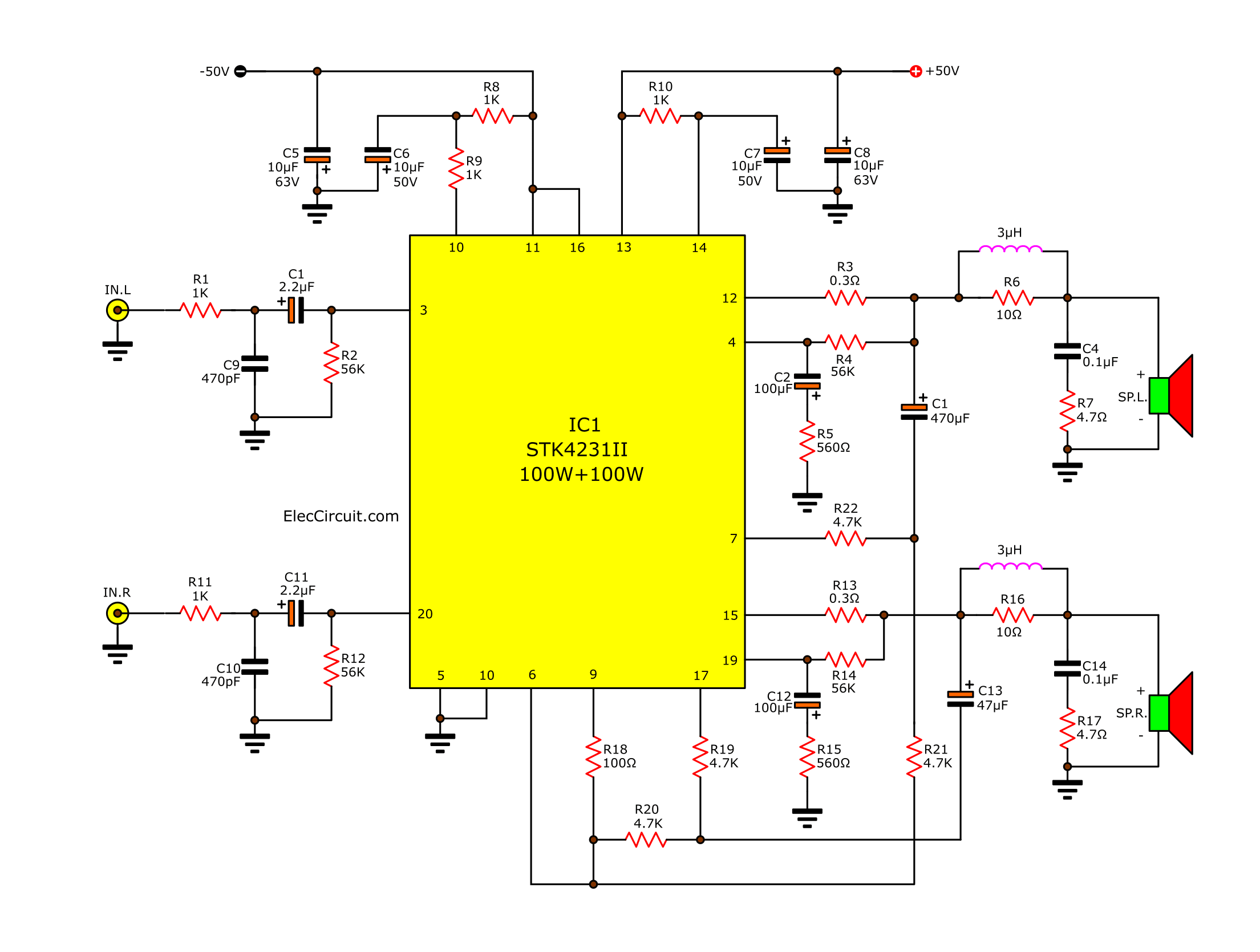
2 channel 100W min AF Power Amplifier STK4231II

If you want to create the 100 watt OCL audio amplifier circuit. I want you to consider this circuit as one. It uses STK4231 IC products to create a simple, small and best economical.
How it works.
The STK4231 is Hybrid IC of Sanyo, in the family of STK4201II. Can provide a high power output to 100 watts per channel. And When connected to the bridge adapter with output altitude of about 400 watts is incredible.
-Built-in muting circuit to cut off various kinds of pop noise.
Greatly reduced heat sink-due to case temperature 125 degrees Celsius.
-Excellent cost performance.
2-channel-100w-min-af-power-amplifier-circuit-by-STK4231
Read more to see PCB and power supply circuits

Power Amp OCL 100W by Transister MJ15003,MJ15004

This Circuit Power Amp OCL 100W by Transister.It old circuit,but nice circuit amplifier.
Use transister MJ15003 and MJ15004, power supply +38V,-38V 3A.
Output power 100W at Speaker 8OHM.

Read More and View Circuit
Power Amp OCL 100W by Transister MJ15003,MJ15004

Power Amp OCL by 741+2N3055+MJ2955

Circuit Power Amp OCL by 741+2N3055+MJ2955

This is old circuit Power amp OCL, But easy circuit and very nice. To use for play music in your home. It low cost too.
It use IC 741 or LF351(good) and Transistor x 4 (2N3055+MJ2955+BD139+BD140)
and little component.
Power supply volt +35V/-35V and 3A for Mono, 5A for Stereo.


PCB Power Amp OCL by 741+2N3055+MJ2955

Circuit Tone control adjustable bass-treble Stereo by IC LM348

Circuit Tone control adjustable bass-treble Stereo by IC LM348
PCB Tone control adjustable bass-treble Stereo by IC LM348

Loudspeaker Protection with Soft Start

This is a small protection circuit from loudspeakers, from DC voltage that likely to exist after some damage in the power amplifier. If a DC voltage is presented in the exit of amplifier, RL1 it interrupts immediately the line of loudspeakers preventing thus to reach in he. Parallel it provides a delay time of 3 seconds from the moment where the power supply will be applied. This delay protects the loudspeakers from undesirable bangs that are observed when open the supply switch. The Leds D 4-5 provide a optical indication for the circuit operation [D4 (green)=OK and D5(red)= delay or presence DC voltage]. The supply of circuit becomes from a symmetrical ±12Volts, which we can take from small independent power supply or from afterwards suitable demotion of main power supply. It will be supposed you make a circuit of protection for each final amplifier that you dispose. Proportional attention it should you show for the quality of RL1 that the contacts of will be supposed to bear the current that passes from he.

Source :: http://users.otenet.gr/~athsam/Lsp_protection.htm

TDA2030 amp OTL 15W

Circuit TDA2030 amp OTL 15W
PCB TDA2030 amp OTL 15W

HA1377 Bridge Amplifier BCL cap 17W (Car audio)

This is circuit Car audio Amplifier(Bridge Amplifier BCL) , It use IC HA1377, Supply Volt 12V-13V. Speaker 4 OHM. Nice Circuit and Easy to Build.

Circuit HA1377 Bridge Amplifier BCL cap 17W


PCB HA1377 Bridge Amplifier BCL cap 17W

Electronic projects circuits